nand2tetris
building a computer from the ground up
Maybe my favorite module during the first year was “Computer Fundamentals”. We used the popular nand2tetris course structure to “build a computer” starting from the most basic gates to a fully functioning computer (if you can call a calculator a fully functioning computer).
The idea was simple, the teacher taught us the basics in class and we had to figure out how to piece it all together into the building blocks of a computer. But, we took the better part of 2 months to really get a hang of it, this is also where I tell you that this was a group project so this was by no means just my effort.
We start with the basic gates written in nand2tetris’ own .hdl or hardware description language, which from what I guessed seemed to be a spin-off of Java or at the very least some form of OOP language
CHIP ourAnd{
IN a,b;
OUT out;

PARTS:
ourChip(input1=a, input2=b, result=innerOutput);
Not(in=innerOutput, out=out);
}
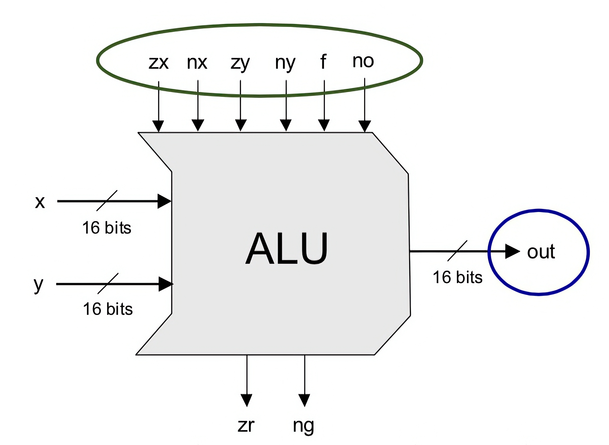
From there, we can build up larger and larger versions of these; 16 bit And, Not, Or, Mux, and so on. 16; because we are building a 16 bit computer. These allow us to build the heart of our CPU, the ALU or Arithmetic Logic Unit.
CHIP ourALU16 {
IN x[16], y[16], zx, zy, nx, ny, f, no, z[16];
OUT output[16];

PARTS:
Mux16(a=x, b=z, sel=zx, out=x1);
Mux16(a=y, b=z, sel=zy, out=y1);
Not16(in=x1, out=nx1);
Not16(in=y1, out=ny1);
Mux16(a=x1, b=nx1, sel=nx, out=x2);
Mux16(a=y1, b=ny1, sel=ny, out=y2);
And16(a=x2, b=y2, out=andxy);
Add16(a=x2, b=y2, out=addxy);
Mux16(a=andxy, b=addxy, sel=f, out=fxy);
Not16(in=fxy, out=nfxy);
Mux16(a=fxy, b=nfxy, sel=no, out=output);
}


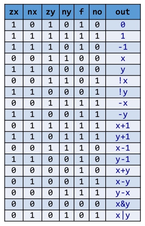
Basically, what the ALU does is that for any two 16 bit inputs, to output either the negation, addition, subtraction, conjunction, or disjunction of them. From the diagram above we can see that the ALU has 6 control bits, changing the values of these control bits according to the truth table will output the desired operation.
Next, come our memory chips. These consist of bits which are written as such:
CHIP ourBit {
IN in, load;
OUT out;

PARTS:
Mux(a=in, b=Previous, sel=load, out=temp);
DFF(in=temp, out=Previous, out=out);
}
Combining 16 of bits gets us a 16 bit register. Combining 8 registers gets us a RAM8 chip, so on and so forth until we get a RAM16K chip which consists of 16 thousand registers, each 16 bits wide. Even the keyboard itself is just a small memory space that the user can edit.
The final step is to combine the CPU, Memory, and ROM(using the built in one as it is a little out of our scope since it contains the machine code that allows us to boot into a GUI).
CHIP Computer {
	IN reset;

	PARTS:

	// inM - Data input fetched from memory
	// instruction - Instruction input fetched from ROM
	// reset - Selector for PC register, resets pc value to 0 if selector is 1, does nothing if selector is 0
	// writeM - Signal to write to memory, write to memory if writeM==1, read from memory if writeM==0
	// outM - Data output from CPU to be fed into memory
	// addressM - Address of the memory to be accessed, to be fed into data register
	// pcOut - Address of the next instruction to be fetched from ROM, to be fed into ROM (instruction register)
	CPU (inM=memOut, instruction=instruction, reset=reset, writeM=writeM, outM=outM, addressM=addressM, pc=pcOut);

	// in - take the outM data
	// load - Signal to load data
	// address - Memory address
	// out - Output data
	Memory (in=outM, load=writeM, address=addressM, out=memOut);

	// address - Input address from the Program Counter
	// out - Output instruction
	ROM32K (address=pcOut, out=instruction);
}
Et voila! There is our full fledged computer that can run assembly programs.
Here we run a simple assembly program to add 2 and 3:
You might (definitely) be thinking; “All that work and we only added 2 numbers?”. The process of building itself was the goal in this project, to make you think of the actual work that a computer does while you read this very text. So the next time you sit down with nothing to do with computer, try to REALLY think of every bit that goes in and out and every instruction that happens inside your computer.
Disclaimer: I didn’t upload every piece of information and code that I have on this topic especially the ones related to the final coursework due to academic misconduct rules. If you want a much more in-depth look at this program structure go to nand2tetris.org.
All credits to Zhang Ruo Chi and/or all original creators for the ALU diagram.